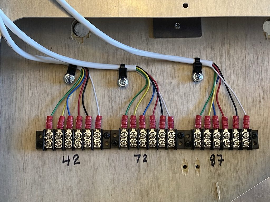
SGMA Club modular layout features a number of “Trigger Track” Modules which have insulated outside rails on all 3 tracks in that module. The insulated rails are connected to DPDT relays to allow for triggering of accessories on nearby scenery modules. Scenery modules access the relays using the wiring harness shows in the photo below:
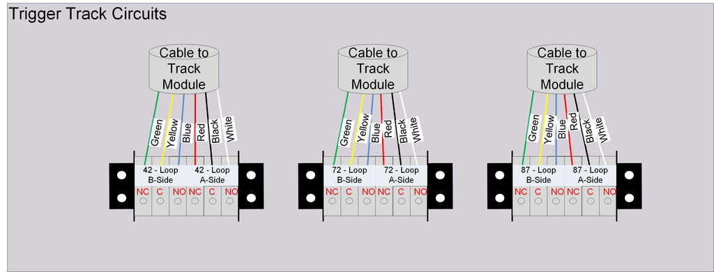
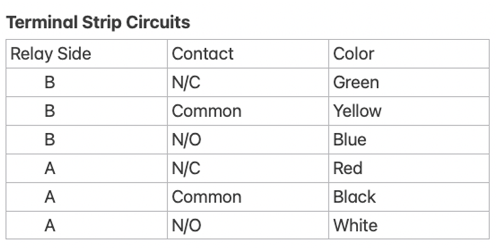
Each of the 6-conductor terminal strips provides the 3 traditional relay contacts (NormallyClosed, Common, NormallyOpen) for both the A and B side of the DPDT relay. The schematic diagram below shows the specific pinouts on these terminal strips:
Sample Relay Wiring
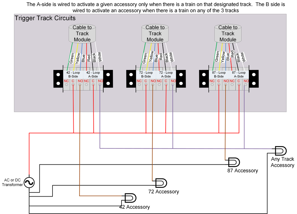
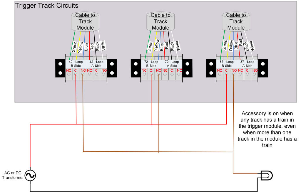
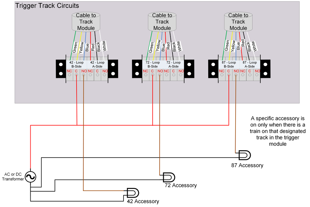
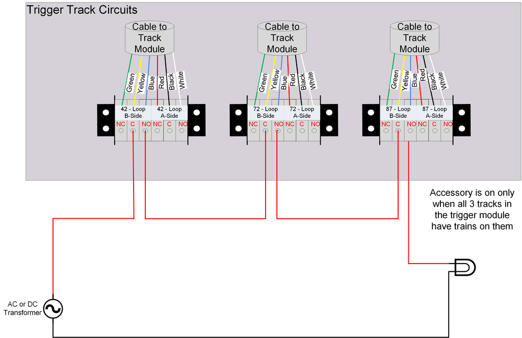
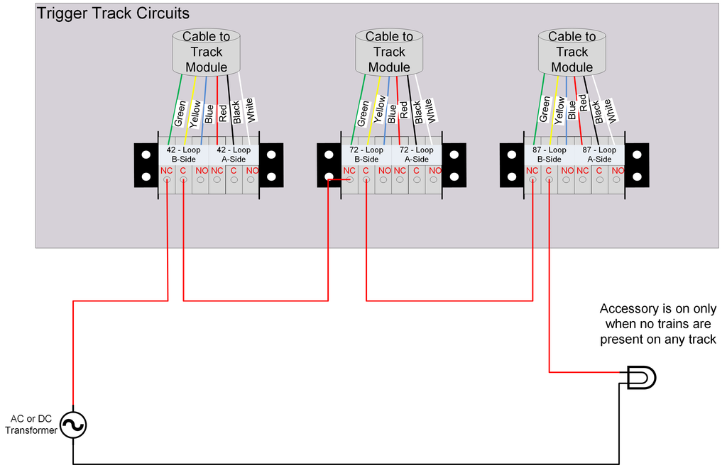
The following diagrams provide wiring examples to trigger one or more accessories directly using the built-in trigger relays. These examples show wiring for the “A” side of each relay. The “B” side is identical and can be wired independently of the A side, meaning that you can use the A side to trigger one set of accessories one way, and the B side to choose a different option. Or, as an example, you can use the A side to power/trigger AC devices and use the B side for DC devices. The final diagram shows an example of using the A side to trigger one behavior and the B side to trigger something different. It is only one of many possible setups.
Trigger if any one of 3 tracks has a train
Trigger 3 Accessories using individual tracks
Trigger only when all 3 tracks have a train
Trigger only when NO tracks have a train
Example of using both A & B Relay sides for each of the 3 relays and tracks. You can mix/match any of the previous examples.